
Tired of being close passed when commuting and not knowing whether you have a legitimate MPD (Minimum Distance Passing) violation to forward to authorities?
This is a multi-part Post where I will be posting build instructions and Python scripts to interface with the Maxbotix MB8450 ultrasonic sensor (an industrial fit-for-purpose ultrasonic sensor) to log distances over time and generate a readable log file that can be overlayed ontop of front and rear camera footage within RaceRender or VIRB Edit (RIP DashWare). If I get it working I’ll also include how to sync GoPro’s with Bluetooth/RC support to start recording when the RPi Zero commences sensor logging so front/rear footage is synced.
Here’s the build list for building your own close distance passing unit for measuring the distance between your right-most handlebar edge and passing vehicles.
- Raspberry Pi Zero (Datasheet)
- A battery pack capable of an output voltage of 5V at 2A and above, e.g. Topeak Mobile Powerpack 6000 mAh (Datasheet)
- Maxbotix MB8450 Car Detection Sensor (Datasheet)
- A USB micro cable to connect the battery pack to the RPi Zero
-
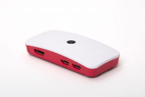
- Raspberry Pi Zero with case.

-
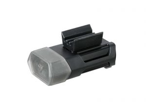
- Topeak Mobile Powerpack 6000 mAh

-
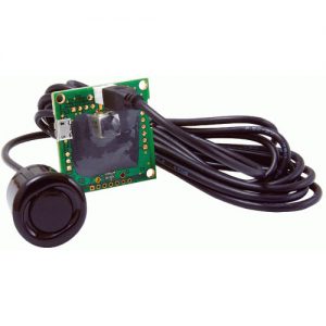
- Maxbotix MB8450 ultrasonic sensor

What’s in the list?
Ultrasonic sensor: The Maxbotix MB8450 is a high performance USB proximity detection sensor that is weather resistant and intended for vehicle detection within vehicle kiosks, ATMs, and bank drive-through environments. It is widely supported, easy to integrate with and its supported range from 50cm to 500cm makes it ideal for this application. In real-world tests it reliably returns distance echos of 0.3s with expected performance benefits (increased echos per second) when interfaced via C program over Python scripts.
The MB8450 is made up of two components, the ultrasonic sensor (transducer) and the PCB logic board.
- The sensor is weather resistant and can be mounted on the right-hand edge of the handlear; or anywhere on the bike frame where its beam is not obstructed. It provides range data to the PCB logic board.
- The PCB logic board processes the range data, cleans it up and passes it onto the RPi Zero via the USB connector. It is not weather resistant and needs to be protected.
Battery pack: The Topeak Mobile Powerpack 6000 mAh has dual USB outputs supporting up to 2A making it ideal for powering the RPi Zero, it turns on automatically when a current draw is detected and powers off shortly after devices cease. The battery pack can be mounted on the handlebar stem, anywhere on a bicycle frame using a GoPro mount or with some effort under the seat.
RPi Zero & PCB board: Due to the length of cabling from the ultrasonic sensor to the PCB board I chose to keep the PCB board of the ultrasonic sensor and RPI Zero within the saddle bag with a single USB micro cable running into the saddle bag. The PCB board and RPi Zero due to their small size could be mounted within a “tool box water bottle” or within a self-contained, weather resistant storage box.
Gallery
-
- Topeak Mobile Powerpack 6000 mAh


What’s next?
I’ll be posting RPi Zero build scripts and the Python scripts to generate log files when able including BitBucket repo link, a little time limited at the moment due to other projects. Thanks for reading.